Indruction
Hello friends, welcome to Rajesh Technical Blog. Today I will tell you how to repair motor coil step by step.
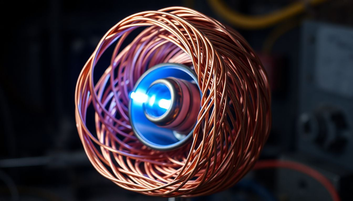
How to Make a Generator Field Coil: A Comprehensive Guide
The hum of a generator often signals power at work. This power comes from a vital part: the field coil. This electromagnetic component creates the magnetic field needed for electricity. Building or fixing a field coil offers insights into power generation. It also provides a cost-effective choice for DIY fans and technicians. This guide breaks down the steps, materials, and ideas for making a working generator field coil.
We will explore electromagnetism basics and practical winding and insulation steps. We cover the details of this important generator part. Making your own field coil is a valuable skill. It helps whether you build a custom generator or fix an old one.
Understanding the Fundamentals of Generator Field Coils
Generator field coils are central to how these machines produce power. Knowing their role is the first step in making one yourself. We will look at how these coils work and the science behind them.
Purpose and Function
The field coil’s main job is to create a strong magnetic field. This field is essential for electricity generation. It sits in the generator’s stationary part, called the stator. The magnetic field interacts with the armature, or rotor. This interaction induces an electric current in the armature windings.
In AC generators, the field coil often produces a steady magnetic field. The rotor spins through this field. This creates alternating current. DC generators typically use the field coil to set up a fixed magnetic field. The armature’s rotation and commutator then produce direct current.
Key Principles of Electromagnetism
The operation of a field coil relies on basic laws of physics. Understanding these laws helps in proper coil design. These principles explain how electricity and magnetism connect.
- Faraday's Law of Induction: This law states that a changing magnetic field induces a voltage. In a generator, the armature windings cut through the field coil's magnetic lines. This movement causes the voltage. The speed of change directly affects the induced voltage.
- Lenz's Law: This law relates to the direction of the induced current. It says the induced current creates a magnetic field. This new field always works against the original change in magnetic flux. This principle helps maintain stability in the generator.
- Ampere's Law: This law links the electric current in a wire to the magnetic field it makes. More current through the field coil means a stronger magnetic field. The number of wire turns also boosts the field strength.
Components of a Field Coil
A generator field coil is more than just a wire. It involves several parts working together. Each component has a specific job in making a strong, reliable magnetic field.
- Core Material: The core forms the center of the coil. Materials like iron or laminated steel are common. These materials have high magnetic permeability. This means they can easily become magnetized. Laminated cores are slices of steel. They reduce eddy currents in AC generators.
- Conductor Wire: This is the wire that gets wound around the core. Copper is often chosen for its excellent conductivity. Aluminum is another option, but it has higher resistance. The wire's gauge, or thickness, matters. Thicker wire handles more current. The wire also needs an insulating enamel coating.
- Insulation: Insulation prevents the wire turns from touching each other. Direct contact causes short circuits. Common insulation types include varnish, enamel, and heat-resistant sleeving. Good insulation protects the coil from electrical damage. It also shields it from heat and wear.
Planning Your Generator Field Coil Project
Careful planning is key for a successful field coil build. This stage ensures you select the right materials. It also helps you prepare for the winding process. Proper planning prevents issues and ensures safety.
Determining Coil Specifications
Before winding, you must know what your coil needs to do. These specifications guide your material choices. They also dictate the coil's physical design.
- Voltage and Amperage Requirements: Your generator's voltage output affects the number of turns. Higher voltage usually means more turns. The amperage determines the wire gauge. Thicker wire handles higher currents without overheating. Mismatched specs lead to poor performance.
- Magnetic Field Strength: The needed magnetic field strength depends on your generator's size. It also depends on its power output. Larger generators need stronger fields. This strength relates to the coil’s ampere-turns. More turns or higher current boost the field.
- Resistance Calculations: Estimating the coil's resistance is important. Resistance affects how much current flows. You can calculate resistance using wire length, gauge, and material resistivity. This helps confirm the coil meets electrical demands.
Selecting Appropriate Materials
Choosing the right materials impacts the coil’s efficiency and life. Compromising here can lead to early failure. Always select materials that match your design specifications.
- Choosing the Right Wire Gauge: Use a wire gauge chart to pick the correct thickness. This chart shows current carrying capacity for different wire sizes. Selecting wire that is too thin causes overheating. Too thick, and it might not fit. Copper magnet wire with enamel insulation is ideal.
- Selecting Core Material: For AC generators, laminated cores are best. They reduce energy loss from eddy currents. Solid iron cores work for DC applications. Iron cores are cheaper but not as efficient for AC. The core must be clean and free of rust.
- Insulation Materials: Good insulation protects your coil. Use high-temperature varnish or epoxy resin. These seal the windings. Sleeving, made of fiberglass or heat-shrink tubing, adds extra protection. Ensure all materials can withstand the expected operating temperature.
Safety Precautions
Working with electrical components and tools carries risks. Always prioritize safety. Following safety guidelines protects you and prevents accidents.
- Electrical Hazards: Always disconnect power before working on generators. Field coils can carry significant current. Wear insulated gloves when handling electrical components. Be aware of voltage levels to avoid shocks.
- Mechanical Hazards: Use tools carefully. Winding wire can snap back if tensioned too much. Keep your workspace tidy to avoid trips. Secure core materials to prevent movement during winding.
- Personal Protective Equipment (PPE): Always wear safety glasses to protect your eyes. Gloves prevent cuts and keep oils from your hands off the wire. A respirator might be needed when applying varnish in a poorly vented area.
The Winding Process: Step-by-Step
Winding the field coil correctly is critical. It ensures the coil works as intended. Precision in each step leads to a durable and efficient coil. We will cover preparing the core and securing the finished coil.
Preparing the Core
A well-prepared core is essential for effective winding. This stage makes sure the core is clean and ready. It also helps the wire lay flat and evenly.
- Cleaning and Inspecting the Core Material: First, thoroughly clean the core. Remove any rust, dirt, or grease. Use fine sandpaper or a wire brush, then clean with a solvent. Inspect for any sharp edges or burrs. These could damage the wire insulation.
- Ensuring the Core is Properly Shaped for Winding: The core must have a smooth and consistent shape. Any unevenness will make winding difficult. It can also create gaps in the coil. For laminated cores, ensure all laminations are tight and aligned.
Winding the Wire
The winding process requires patience and precision. Uniform, tight winding boosts the coil’s efficiency. It also prevents internal shorts.
- Starting the Wind: Securely attach the beginning of the wire to the core. A small notch or a piece of tape can hold it in place. Make sure the initial connection is solid. This prevents the wire from unraveling.
- Uniform Winding Techniques: Wind the wire in neat, even layers. Avoid crossing wires if possible. Each turn should lie close to the last. This technique maximizes the magnetic field strength. It also reduces coil size. Use a winding jig or a hand-cranked setup for best results.
- Managing Wire Tension: Keep consistent tension on the wire during winding. Too loose, and the coil will be sloppy. Too tight, and the wire might stretch or break. Proper tension ensures a compact, stable coil.
- Counting Turns: Accurate turn counting is vital. The number of turns directly impacts magnetic field strength. Use a mechanical counter on your winding setup. If winding by hand, count carefully. Double-check your count before moving on.
Securing and Insulating the Coil
Once wound, the coil needs securing and insulating. This protects it from shorts and environmental damage. These steps ensure the coil's longevity.
- End Connections: Prepare the wire ends for connection. Scrape off the enamel insulation from about an inch of each end. This exposes the bare copper. Twist these ends or solder them to terminals. Ensure solid, reliable electrical connections.
- Applying Insulation: Coat the entire wound coil with insulating varnish. This fills any small gaps between wires. It also provides a protective outer layer. Dip the coil in varnish or brush it on. Allow ample time for the varnish to dry and cure completely.
- Using Insulating Sleeves: For added protection, especially at connection points, use insulating sleeves. Heat-shrink tubing or fiberglass sleeving works well. Apply these over the bare wire ends or where wires exit the coil. This prevents accidental contact with other components.
Testing and Installation
After winding and insulating, testing confirms your coil is ready. These tests verify proper construction and function. Correct installation then integrates the coil into the generator.
Continuity Testing
Continuity testing confirms an unbroken path for electricity. It is a quick and basic check for your new coil.
- Using a Multimeter to Check for Breaks in the Winding: Set your multimeter to the continuity or resistance setting. Touch one probe to each prepared end of the coil wire. A good coil will show a reading, often a low resistance value. An open circuit, indicating a break, will show "OL" or no reading.
- Ensuring a Complete Circuit: This test confirms the wire is continuous from one end to the other. It means no internal breaks exist within the windings.
Resistance Measurement
Measuring resistance provides more detail about your coil's properties. It helps confirm your design calculations.
- Measuring the Coil's Resistance Against Calculated Values: Use the multimeter's resistance function. Note the precise resistance value. Compare this to your initial calculations. A significant difference might signal an issue.
- Identifying Potential Issues with the Number of Turns or Wire Gauge: Higher than expected resistance could mean too many turns. It could also mean a thinner wire than planned. Lower resistance might suggest fewer turns or a thicker wire. Both can affect performance.
Insulation Resistance Testing (Megger Test)
This is a critical safety test. It checks how well the coil's insulation prevents current leakage.
- Checking for Shorts to Ground or Between Windings: A megohmmeter (megger) applies a high voltage. It measures any current leakage. This test checks for shorts between the coil and the core. It also checks for shorts between layers of wire.
- Importance of High Insulation Resistance for Generator Performance and Safety: High insulation resistance is vital. It stops current from leaking. This protects both the generator and its users. Low resistance can cause dangerous electrical faults. It also reduces generator efficiency.
Installation in the Generator
Proper installation ensures the field coil works with other generator parts. Follow manufacturer guidelines if possible.
- Properly Mounting the Field Coil: Secure the field coil firmly to the generator's stator frame. Use appropriate bolts and brackets. Ensure it is aligned correctly. Improper mounting can cause vibrations or misalignment.
- Connecting the Coil to the Generator's Excitation Circuit: Connect the coil's ends to the generator’s excitation circuit. This circuit supplies the current to energize the coil. Make sure connections are tight and clean. Incorrect wiring can prevent the generator from producing power.
- Reassembly of Generator Components: Carefully reassemble the rest of the generator. Put the rotor back in place. Close the housing. Double-check all connections and moving parts.
Troubleshooting Common Field Coil Issues
Even with careful construction, problems can arise. Knowing how to troubleshoot helps fix issues quickly. We will look at common field coil problems and their solutions.
Overheating
An overheating field coil is a serious problem. It can damage the coil and the entire generator.
- Causes: The wire might be too thin for the current. Too many turns can also cause heat buildup. Internal shorts create resistance and heat. Poor ventilation also contributes to overheating.
- Solutions: Recalculate your coil specifications. Rewind the coil with the correct wire gauge. Ensure proper airflow around the coil for cooling. Check for and fix any internal shorts.
Weak Magnetic Field
A weak magnetic field leads to low power output. The generator will not produce enough electricity.
- Causes: The coil might not receive enough current from the excitation circuit. There could be internal shorts reducing effective turns. The core material might be demagnetized or of poor quality.
- Solutions: Check the excitation circuit for proper voltage and current. Rewind the coil with the correct number of turns. Evaluate the core material. Replace it if it has poor magnetic properties.
Intermittent Power Output
Fluctuating power suggests an unstable connection or internal fault. This can be frustrating and unreliable.
- Causes: Loose connections in the coil or excitation circuit cause intermittent contact. Damaged insulation can lead to occasional shorts. Internal shorts within the winding can also cause inconsistent performance.
- Solutions: Inspect all connections. Tighten or repair any loose points. Carefully check the coil for damaged insulation. Rewind or replace the coil if insulation is compromised.
Short Circuits
Short circuits are dangerous and can cause severe damage. They stop the coil from working properly.
- Causes: Damaged insulation is a primary cause. Improper winding techniques can leave wires exposed. Foreign objects lodged in the windings can also pierce insulation.
- Solutions: A thorough inspection is needed. Look for charred spots or melted insulation. Rewind the coil completely, paying close attention to insulation. Ensure no foreign materials are present during winding.scorpio-m2di-engine-repair.
Conclusion
Building a generator field coil combines electrical theory with hands-on work. You can create a working field coil by understanding the basics. Carefully planning the project helps, as does precise winding. Thorough testing also plays a key role. This skill helps you fix and build generators. It also boosts your knowledge of power generation. Always make safety your top priority throughout the entire process.
If you have learned something from this today, then share it with your friends and if you want to ask something, then you can ask me by commenting. Thank you.
Join us on Social Media


Comments
Post a Comment